
Industrial Earthing Installation: Methods, Standards and Testing
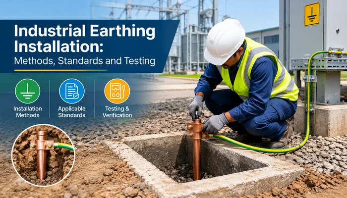
Every industrial plant depends on a hidden network of conductors buried below its floors and yards. When it works, nobody notices it. When it fails, the result can be equipment damage, production loss, fire, or a fatal shock. A well-planned Industrial Earthing System is the foundation of dependable Industrial Electrical Safety, and it deserves the same attention as transformers, panels and cabling.
This article covers how earthing works in industrial settings, the methods used, the standards that apply, and how testing confirms the system will perform when a fault occurs.
Why Earthing Matters in Industrial Facilities
Earthing gives fault current a low-resistance path back to the ground. Without it, a live conductor touching a motor frame or panel enclosure can leave that metalwork energised, waiting for someone to touch it. With a proper connection to earth, the protective device sees a large fault current and trips quickly, isolating the circuit before harm is done.
Industrial sites face higher risks than offices or homes. They have large motors, variable frequency drives, welding equipment, high-capacity transformers and long cable runs. Lightning is also a real threat, particularly for open sites in a state like Gujarat. A solid Industrial Earthing Installation protects people, keeps sensitive control electronics stable, and limits the damage from surges and switching events.
Good earthing also supports production. Poorly earthed plants suffer nuisance trips, communication errors in PLC and SCADA systems, and unexplained failures of electronic drives. Many of these problems trace back to a weak or noisy earth.
Core Components of an Earthing System
A typical Industrial Earthing System is built from a handful of elements working together:
- Earth electrodes: pipe, plate, rod or strip electrodes driven or buried in the soil
- Earth conductors: GI strips, copper strips or cables linking equipment to the electrodes
- Earth pits: chambers that house electrodes and allow inspection and maintenance
- Bonding connections: links that keep all exposed metalwork at the same potential
- Test links: removable joints that allow individual electrodes to be isolated and measured
Industrial designs usually separate the earthing for different functions. Equipment or protective earthing, system neutral earthing, lightning protection earthing and electronic or instrument earthing may each have their own electrodes, tied together at a controlled point where standards require it.
Common Methods of Earthing
The right method depends on soil resistivity, available space, fault levels and the sensitivity of the equipment.
Plate earthing uses a copper or galvanised iron plate buried vertically at a suitable depth, often surrounded by charcoal and salt or a chemical compound to keep resistance low. It suits locations with deeper moisture and adequate space.
Pipe earthing is the most widely used method in industry. A galvanised iron pipe is driven into the ground, and a funnel at the top allows periodic watering or treatment. It is economical and easy to maintain.
Rod earthing uses copper-bonded steel rods, sometimes driven in multiples and connected together to bring resistance down. It works well where soil conditions allow deep driving.
Strip or mat earthing relies on conductors laid in a grid. Substations and large plants use earth mats to control step and touch voltages across a wide area. This is especially important near HT equipment.
Maintenance-free chemical earthing uses a copper electrode surrounded by a conductive backfill. It performs well in rocky or dry soil where conventional methods struggle to reach acceptable resistance.
Choosing among these is an engineering decision, not a matter of habit. A site with sandy, dry soil may need a chemical or deep-driven solution, while a plant on moist alluvial ground may do well with pipe electrodes. Measuring soil resistivity before design begins takes the guesswork out of the choice.
Standards That Guide the Work
Earthing practice in India is shaped by the Indian Electricity Rules, the Central Electricity Authority regulations and the relevant Bureau of Indian Standards codes. IS 3043 is the main code of practice for earthing, and it covers electrode selection, conductor sizing, resistance targets and installation details. Lightning protection falls under its own standard, and substations follow additional utility and CEA requirements.
Compliance is more than a paperwork exercise. These standards represent decades of accumulated lessons from real failures. A plant that follows them is easier to insure, easier to get approved by the authorities and the local power distribution company, and much easier to maintain.
The Installation Process, Step by Step
Reliable Industrial Earthing Installation Services follow a disciplined sequence rather than a rush to dig pits.
Site assessment and soil testing come first. Resistivity readings at different depths and locations show how conductive the ground is and where the best electrode positions lie.
Design follows. The engineer calculates the maximum fault current, selects conductor sizes to carry it without overheating, decides on the number and layout of electrodes, and checks that step and touch potentials stay within safe limits.
Excavation and electrode placement come next. Pits are positioned away from foundations and cable routes where possible, and electrodes are installed at the specified depth and spacing.
Jointing is critical. Connections must be mechanically strong and corrosion-resistant. Welded or properly clamped joints, protected with suitable coating, prevent the slow degradation that quietly raises resistance over the years.
Bonding then ties everything together: transformer neutrals, panel enclosures, cable trays, structural steel, motor frames and lightning down conductors all connect to the earthing network according to the design.
Finally, the system is tested before it is accepted and energised.
Industrial Earthing Testing: Proving the System Works
An earthing system that has not been measured is only an assumption. Industrial Earthing Testing turns that assumption into evidence, and it should happen at commissioning and at regular intervals afterwards.
The main tests include:
- Earth electrode resistance, usually measured by the fall-of-potential method using a dedicated earth tester
- Soil resistivity measurement, commonly done with the Wenner four-pin method
- Earth loop impedance, which confirms protective devices will operate fast enough
- Continuity testing of bonding conductors across equipment and structures
- Step and touch voltage checks in substation and high-fault-level areas
Targets vary with the application. Equipment earthing in many plants aims for a low single-digit ohm value, while substations and sensitive electronic installations often demand even less. Whatever the target, the readings should be recorded, signed and kept on file so that future measurements can be compared against the original baseline.
Seasonal variation matters here. Soil dries out in summer and resistance rises, so a pit that reads well after the monsoon may look very different in May. Testing at different times of year, and keeping electrodes moist or treated where required, helps prevent unpleasant surprises.
Maintenance and Periodic Inspection
Earthing is not a fit-and-forget item. Corrosion, soil changes, mechanical damage and plant expansion all affect performance over time. A practical maintenance routine includes:
- Visual inspection of pits, covers and connections at least annually
- Periodic resistance testing and trend recording
- Topping up water or treatment compounds where the design requires it
- Re-testing after any major plant modification or after a lightning strike
- Immediate repair of any broken, loose or corroded conductors
Plants that skip this routine often discover their earthing has degraded only after a fault, which is the worst possible time to find out.
Common Mistakes to Avoid
A few errors show up repeatedly on industrial sites. Using undersized conductors that cannot carry fault current is one. Sharing a single poorly installed pit across several functions is another. Painted-over or corroded joints, missing test links, and electrodes placed in the driest corner of the plant all weaken the result. So does treating earthing as a last-minute task at the end of a project, when space and budget are already squeezed.
Avoiding these problems is mostly a matter of planning early, specifying clearly and inspecting before anything gets buried or covered.
Choosing the Right Partner
Because earthing touches every part of a plant, it works best when handled by a team that understands the whole electrical picture. An experienced Electrical Contractor coordinates earthing with cable laying, transformer commissioning, panel erection and lightning protection, so the system is designed as one coherent whole rather than a collection of separate fixes. The same goes for broader Electrical Installation Services: when design, installation and testing sit under one responsibility, gaps and finger-pointing disappear.
For a new factory or a plant expansion, Industrial Electrical Installation should treat earthing as a planned deliverable with drawings, test records and handover documents, not as an afterthought. A capable Industrial Electrical Contractor will bring soil data, calculations and test certificates to the table without being asked.
Conclusion
Earthing rarely gets attention until something goes wrong, yet it quietly decides whether a fault becomes a trip or a tragedy. Sound design, the right method for the soil, quality jointing, proper standards compliance and honest testing together create a system that protects people and equipment for decades.
Sahjanand Engicon LLP, an EPC electrical contractor based in Ahmedabad, handles earthing as part of its complete industrial and factory electrification work, from HT and LT infrastructure to panels, cabling and final testing under a single contract. If you are planning a new facility or want your existing earthing checked, speak with their team to arrange a site assessment.